

Testing of early strength development
Various laboratory tests with cement paste or standard mortar tests are carried out to verify the performance of selected cement and admixture interactions.
During spraying trials, shortly after spraying, temperature development is measured as a first indicator of the hydration process. In addition, measuring of early strength development is carried out.
Laboratory scale testing of cement pastes and mortars
Due to the high cost and demanding conditions of time, space and effort necessary for full-scale trials to test sprayed concrete, the setting properties of cements in combination with appropriate admixtures (e.g. accelerators, plasticizers and retarders) are typically first tested in the laboratory in the form of cement paste or as components of a standard mortar.
The main goal of such laboratory tests is the identification of the correct proportion of admixtures to be used in combination with a specific cement to obtain the desired properties of setting and compressive strength development, typically with the additional constraint of cost optimization. Such desired properties are usually defined by an appropriate standardized specification, depending on the specific application intended for the sprayed concrete.
Standard materials preparation for laboratory scale testing
Mortar
The standard preparation of mortar is done according to Norms EN 196-1, EN196-3, EN 413-2, EN 480-1, EN 480-2, prEN 934-5 and prEN 1008.
Physical tests
The prism for physical testing
In order to conduct the physical tests, a standard cement of mortar prism shape (according to EN 196-1) is used to obtain a well-defined piece of material to be tested as specified in the paragraphs below. Such a prism shape is illustrated in Figure 3-29, and has the dimensions of 160.0 ± 0.1 x 40.0 ± 0.2 x 40 ± 0.2 mm. The mortar prism sample obtained is shown in the following figure.
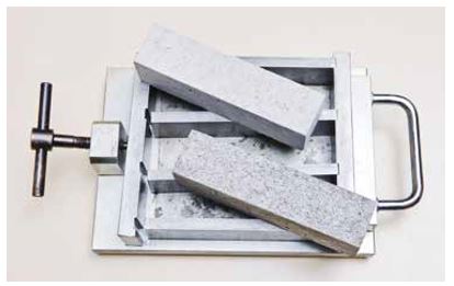
Figure 3-29: Mold used to produce standard mortar prisms for physical testing
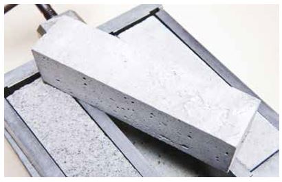
Figure 3-30: Mortar prism sample obtained from the mold
The dosage of accelerator (as the percentage by weight of cementitious content required to provide the initial and final setting times of a cement paste) shall be determined in accordance with EN 196-3 and the corresponding procedure. Alternative test procedures to suit the proposed accelerators and cement types may be proposed for approval by the engineer.
Initial and final setting time
The setting of a cement paste or mortar, in contrast to its hardening, has been defined as “a sudden loss of plasticity of the original paste and its conversion to a solid material with a barely measurable strength. The term hardening means the development of hardness and strength that follows the setting of the paste.” [41]
While this is a qualitative definition, there are standard physical tests defined by EN 196-3 to assess the state of setting of a given cementitious material using the initial and the final setting times, which are determined using the Vicat needle.
Initial and final setting times are measured using a Vicat needle consisting of a cylinder weighing 300 ± 1g and a needle point with a diameter of 1.13 ± 0.05 mm. The initial setting time is defined as the time at which a paste or mortar deposited in the mold begins to oppose resistance to penetration by the Vicat needle. In practice, the Vicat needle is allowed to fall by gravity after being placed as near as possible to the upper part of the material; only when the needle does not touch the bottom of the mold due to the resistance of the material has the setting started. Due to the poor homogeneity of the materials under investigation, especially when using fast setting admixtures, the test is repeated four times, and initial setting is said to have taken place only when at least three out of four trials are positive.
Final setting, on the other hand, is defined as having taken place when the Vicat needle, in contact with the upper side of the material, is not breaking its structure but only leaves the print of the pressure of the point of the needle. It is clear that while this is a qualitative definition of the setting of cement or mortar, indicating the beginning of a phase transition (and therefore the moment when cement will not drip from a vertical or even a perpendicular surface), the quantitative definitions of initial and final setting times depend fully on the instrument used (its weight and the diameter of the needle).
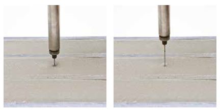
Figure 3-31: Initial setting (on the left) and final setting (on the right), measured with the Vicat needle
Compressive strength
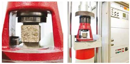
By norm (EN 196-1), the state of hardening of a given cementitious material is assessed by the measurement of the resistance to compressive strength. This is measured by applying pressure onto the prisms (EN 196-1) after 6h, 1 day, 7 days, and 28 days. Between measurements the prisms are kept at a constant temperature of 20 ± 2°C and constant humidity of at least 90 %.
Measurement of the continuous development of resistance to penetration
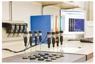
Initial and final setting times, along with compressive strengths at 6h, 1 day, 7 days and 28 days allow the identification of characteristic points of cement paste or mortar hydration and therefore of their phase transition. Indeed such values can give information on the quality of cement or mortar, and its interactions with accelerators. Nonetheless it is possible and desirable to monitor the state of phase transition of cement in a continuous manner using automatic computer-interfaced penetrometers (see Figure 3-33).
Such instruments are not yet commercially available, but constitute the result of an effort by BASF to improve the quality and speed of materials testing. The resulting curve expresses the development of resistance to penetration, in Newtons (y-axis), against time (x-axis).
The force is depicted as the average value from the four needles. The two curves refer to two different set accelerators (see Figure 3-34). These curves can be correlated to the development of strength of the material. Such measurements can be performed at different penetration speeds for a maximum of 36 hours, and are especially suitable for mortar testing where accelerating admixtures are present.
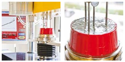
Figure 3-33: Four-needle penetrometer with controlling station
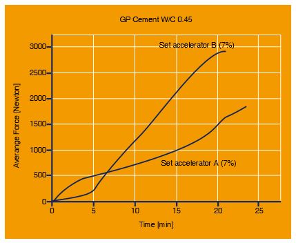
Figure 3-34: Resulting curves of force opposed to needle penetration (Newton) against time
Isothermal Calorimetry
A useful measurement of the chemical reactivity of cements can be obtained by means of isothermal calorimetry, a technique that measures heat flow during cement hydration. Gram-scale amounts of the cement samples are mixed in suitable ampoules and the reaction enthalpy is then measured in constant temperature conditions. Computerized differential calorimetric post-processing then provides curves of ΔH/ΔT, expressing the amount of heat of reaction released in time (see Figure 3-35).
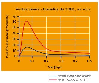
Figure 3-35: Rate of heat evolution for given Portland cement with and without set accelerator (on the left)
High throughput systems such as those illustrated in Figure 3-36 allow the quality control of cements as well as screening the behavior of cements where admixtures are present. Each station allows eight measurements.
Full-scale testing of sprayed concrete in controlled conditions
While mortar tests with varying levels of sophistication, as well as analysis of isothermal calorimetry, are fundamental pre-screening tools for cementitious materials and admixtures, full-scale tests of sprayed concrete deliver results with the highest degree of consistency for tunneling and mining job sites.
Full-scale performance testing of sprayed concrete can be done either in a laboratory (full-scale controlled conditions sprayed concrete laboratory) or at a job site (field testing). Full-scale laboratory tests require the availability of a concrete pumping and accelerator dosing system (such as MEYCO® Suprema) and a spraying manipulator (such as MEYCO® Oruga) for a concrete output comparable to that of a job site. The dimensions of such a laboratory should be sufficient to accommodate this apparatus, and allow testing of concrete at controlled temperature conditions.
Furthermore, a set of consistent measuring tools to determine the strength development of the sprayed concrete is also necessary.
The sprayed concrete laboratory
Full-scale spraying of concrete can be performed in a laboratory provided that sufficient space is available to accommodate a model section of a gallery and professional machines for mixing and spraying concrete. Figure 3-37 illustrates such a laboratory and tunnel model section.
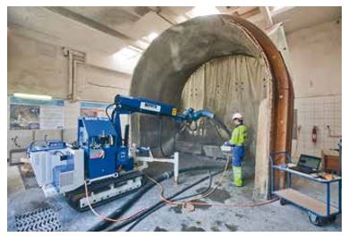
Figure 3-37: Spraying tests laboratory with model section of tunnel and concrete spraying and mixing machines
A spraying manipulator can access the laboratory testing area, while concrete is pumped by a neighboring pumping and accelerator dosing system. A concrete mixer truck carrying between 1 and 4 m3 of fresh concrete delivers the concrete to the sprayed concrete pump. In a typical experiment, test panels of dimensions 50 x 50 x 10 cm are filled with sprayed concrete and thereafter moved to an adjacent laboratory (20 ± 2°C, relative humidity not less than 65 %) where they are tested using penetrometers, thus assessing the setting and hardening times. Core samples obtained from the test panels provide samples of constant characteristics.
Measuring setting and hardening of sprayed concrete
In order to measure setting and hardening times, standard molds are filled with sprayed concrete, as described above. Immediately after the filling operation the experiment time is set to zero. In fact, the accelerator is added at the nozzle of the spraying manipulator unit, and sprayed concrete begins to undergo setting immediately. The test panels are rapidly transported to an adjacent thermostatized laboratory to assess the setting and hardening characteristics of the sprayed concrete.
Such assessment is performed using different tools, according to the stage of setting/hardening reached by the material. Current tests are based on needle penetration or nail extraction. In the first range from 0 to 1 MPa equivalent a MEYCO penetrometer may be used, which consists of a cylinder containing a piston and calibrated spring, and ending with a needle (see Figure 3-38). The compression of the spring after insertion of the ring can be measured, indicating the resistance to penetration. See also Chapter 8 for more information. More sophisticated devices can be used which are based on a similar principle, but which transfer the values of resistance to penetration electronically to a computer.
Hilti guns are then used to insert needles, the resistance of which to extraction will provide a value for the hardening reached by the sprayed concrete (see Figure 3-39). The MPa equivalent resistance values are inserted in a table against the time, and provide curves that represent the setting and hardening characteristics of sprayed concrete.
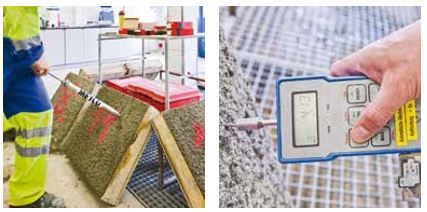

Figure 3-39: Use of Hilti guns to assess setting and hardening of sprayed concrete (measurement of early strengths greater than 2 MPa)